Project Description
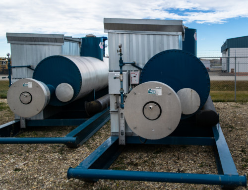
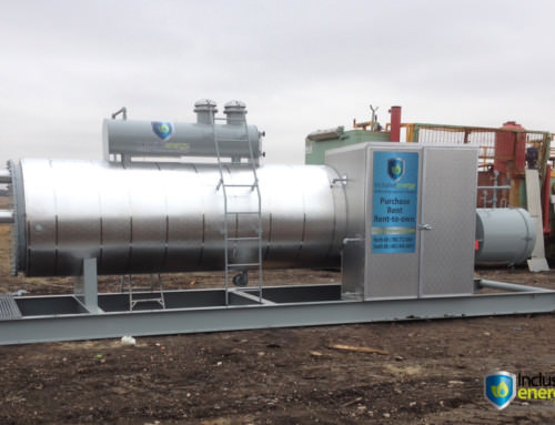
INDIRECT FIRED LINEHEATERS (LH 1.50 MMBtu/hr.) SOUR SERVICE


DESCRIPTION
QTY (6) Indirect Fired Lineheaters. (LH 1.50 MMBtu/hr.) Sour service
QTY (1) FSR INDIRECT FIRED LINE HEATERS
Model: FSR1500IH (1 500 000 BTU/HR) Size: 48”OD x 18’-0” lg. c/w the following equipment:
• heater shell Nominal water capacity: approx. 1440 us gal.
• 16” Removable firetube (151 sq. ft. heating surface area,
Heat Flux: 9,947 BTU/hr/sq.ft., Heat Density: 11,356 BTU/hr/sq.in.)
• 16” x 18ft. Removable T” type Stack with Clean out Down Draft Diverter.
• Removable Split Coil consisting of: Pre-heat (8)-3” tubes (2) 3”CL.2500RTJWN Flanges, 10% Radiography, 1/16”C.A., 5,6555 Psig.@ 200oF,
Re-heat (8)-3” tubes (2) 3”CL.600RFWN Flanges, 10% Radiography, 1/16”C.A.,
1360 Psig.@ 200oF, and fabricated in accordance with the B31.3 Piping Code
• 1”NPT Fuel Gas Preheat Coil.
• Water Saver Pot w/ Thief Hatch and Sight Glass
• 1,500,000 BTU FSR Flash arrestor w/ Main Burner and Pilot Assy.
• Set of instrumentation, controls, valves as listed below.
• 1½”th Urethane panels enclosure for and controls.
• Mineral wool 2”th. Insulation with Aluminum Jacket on Shell.
• Heavy Duty Heater Skid.
• Misc. items as required by FSR heater design.
PROCESS COIL
PRE-HEAT PASS: 8 tubes of 3” sch. XXH x 17’ – 0”
5,655 psig @ 200 F (Ltd. by flg’s.) per ANSI B31.3 and B16.5
3” CL.2500 RTJWN inlet/outlet connections
Corrosion Allowance: 1/16”, 10% X-Ray.
Materials: SA-333Gr.6 / SA-350LF2 CL.1 / SA-420WPL6
MDMT: -50oF
Coil volume: 4.2 cu.ft.
Coil area: 132 sq.ft.
RE-HEAT PASS: 8 tubes of 3” STD x 17’ – 0”
1360 psig @ 200 F (Ltd. by flg’s.) per ANSI B31.3 and B16.5
3” CL.600 RFWN inlet/outlet connections
Corrosion Allowance: 1/16”, 10% X-Ray.
Materials: SA-106B / SA-105N / SA-234WPB
MDMT: -20oF
Coil volume: 7.4 cu.ft.
Coil area: 132 sq.ft.
.
F.G. PRE-HEAT
COIL: 1 tube of 1” sch. 80 x 15’ – 0” (approx. length)
1,480 psig @ 200 F per ANSI B31.3 and B16.5
1”-3000#NPT inlet/oulet connections
Materials: SA-106B/SA-105N/SA-234WPB
Coil bundle will be ABSA inspected and registered in the Province of Alberta, British Columbia and Saskatchewan.
LINE HEATER (H-100)
– Shell size: 48”OD x 18’-0”long.
– 16 OD x 8’-0” long horizontal expansion pot c/w Fourstar vacuum hatch and access ladder.
– Glycol/water immersed bath type heating, Atmospheric design pressure.
– Full support saddles.
– 2” thick Mineral wool insulation on shell only c/w Embossed 0.020” thick banded aluminium cladding. (no ends included)
NOZZLES
Fill Connection 1 8” Hinged mounted on 16” OD pot
Drain 1 2” CL.150RFWN FLG.
Overflow 1 1” CL.3000NPT Cplg.
Firetube 2 16” Plate Flanges
Fuel Gas Preheat 2 1” 3000# Full Coupling
TC 1 3/4” 3000# Full Coupling
HTSD 1 3/4” 3000# Full Coupling
TI 1 3/4” 3000# Full Coupling
Spare 1 3/4” 3000# Full Coupling
Level Gauge 2 1/2” 3000# Full Coupling
LSL 1 2” 3000# Half Coupling
HEATING SYSTEM
– A 16” O.D. horizontal removable firetube.
– 1 – 16”x18’ type “T” removable Stack w/ Clean out & Wind Shroud
– Fourstar standard hinged Flash Arrestor w/ 1.50 MM Btu/hr. duty Main Burner and Pilot/Ignition/FFSD Assembly rated at 1,500,000 BTU/hr net Duty c/w: ECLIPSE COMPOUND INJECTOR H-160: AIR-GAS MIXER, SLEEVE, BARREL AND FERROFIX BURNER NOZZLE. Approx. Fuel Gas Consumption: 2,884SCF/Hr. (based on rated capacity-full load using
1000 Btu/SCF natural gas)
FA to fit 16” firetube c/w 4” th. Aluminium flame cell, 2”NPT peep site in the draft hood.
– Burner to have fuel gas and pilot gas connections @ 12:00 o’clock.
INSTRUMENTATION – Compliance to CSA B149.3-2000
Note: sweet, dry fuel, I/G. to be provided from off skid.
PR-1100 1 B149.3 COMPLIANT BURNER MANAGEMENT SYSTEM
BE-1100 PROFIRE 2100 FLAME GARD IGNITION CONTROLLER
IGN-1100 c/w weatherproof enclosure 12” x 10” x 6”
IGN 50 Sparker / Flame Sense Module
Ignitor / Flame Rod, 10ft. Ignition cable, Pilot Mounting Bracket
For applications up to 10 MMBtu per burner
CSA rating Class 1 Div. 2 Gr. A, B, C, D & T5 temperature rating
Meets Electrical Performance Requirements of Combustion Safety Control as Required by Canadian Standards
Display: VFD (Vacuum Fluorescent Display) 2 Line x 20 Character
Inputs: 12VDC, 24VDC or 24 VAC (Jumper selectable)
Flame Rod, Safety Switches (4), POC (Proof of Closure) Main,
POC Low Fire, Remote Start / Stop
Communications: RS232 / RS485
Outputs: solenoid control (4), Alarm
Factory set configuration: Pre–Purge Timing
Factory set Configuration (Palm Pilot): All other parameters
3.8 second Flame fail Response.
Thermocouple Assembly for detection of flame quality
Type K thermocouple, Shielded Thermocouple Cable included.
EY-101 2 ASCO TWO WAY SOLENOID VALVE
EY-102 1”NPT HV298568001 fuel gas shut off valve
24VDC
ESDV-101 1 ASCO TWO WAY SOLENOID VALVE
1/4″NPT NACE HVL287776-001 gas pilot shut off valve
24VDC, 4 Watts, EXP.
LG-100 1 JERGUSON TUBULAR GAUGE GLASS ASSEMBLY
Model 125 tubular gauge valves
1/2” MNPT end connections
5/8”? Pyrex red line sight glass c/w angle iron guard rods
LSLL-100 1 LINC ELECTRIC LEVEL SWITCH L471-11
2” MNPT process end connection
Explosion proof housing
Standard Service
1,500 psig M.A.W.P.
SPST, CSA certified
PRV-100 1 BELGAS P627 PRESSURE REDUCING REGULATOR
1” FNPT end connections
DI body
Maximum 1,000 psig Inlet pressure
3/8”? orifice
5 to 20psig spring range
PRV-101-2 2 BELLOFRAM MODEL T50 INSTRUMENT GAS REGULATOR
1/4” FNPT connections
Standard service construction
250 psig M.A.W.P. Internal filter
0 to 35 psig spring range
PI-100 4 WIKA PRESSURE GAUGE
PI-101 Model 233.53 liquid filled
PI-102 2 1/2” diameter face x 1/4” NPT bottom connection
Stainless steel case and internals
0 to 30 psig range – Dual scale
PI-104 1 WIKA PRESSURE GAUGE
Model 233.53 liquid filled
2 1/2” diameter face x 1/4” NPT bottom connection
Stainless steel case and internals
0 to 15 psig range – Dual scale
PI-103 1 WIKA PRESSURE GAUGE
Model 233.53 liquid filled
2 1/2” diameter face x 1/4” NPT bottom connection
Stainless steel case and internals
0 to 60 psig range – Dual scale
PI-105 1 WIKA PRESSURE GAUGE
Model 233.53 liquid filled
2 1/2” diameter face x 1/4” NPT bottom connection
Stainless steel case and internals
0 to 160 psig range – Dual scale
PRV-103 1 BELLOFRAM MODEL T50 INSTRUMENT GAS REGULATOR
1/4” FNPT connections
Standard service construction
250 psig M.A.W.P. Internal filter
0 to 120 psig spring range
PSHH-100 1 CCS DUAL-SNAP MODEL 6900GZE12 PRESSURE SWITCH
1/2” FNPT pressure sensing connection
Explosion proof housing
24 volt DC input (SPDT)
Adjustable set point range:
3 to 20 psig. on increasing pressure
1 to 18 psig. on decreasing pressure
Bench set at 18 psig raising
CSA certified
PSLL-100 1 CCS DUAL-SNAP MODEL 6900GZE12 PRESSURE SWITCH
1/2” FNPT pressure sensing connection
Explosion proof housing
24 volt DC input (SPDT)
Adjustable set point range:
3 to 20 psig. on increasing pressure
1 to 18 psig. on decreasing pressure
Bench set at 7 psig falling, CSA certified
PSV-100 1 ACCUSEAL MODEL ASV10 PRESSURE RELIEF VALVE
1” MNPT inlet x 1” FNPT outlet
Sweet service construction
0.212 sq. in. orifice (“E” designation)
150 psig set pressure
PVSV-100 1 FSR 404 PRESSURE-VACUUM RELIEF HATCH
Cast Aluminium body
Sweet service
4 oz. Pressure / 0.4 oz. Vacuum relief
TCV-100 1 KIMRAY CONTROL VALVE
Model: 1400SMT PO 3/8 IV
1”NPT 4000 psi pressure
10 psi spring
3/8” inner valve
Steel body
TI-100 4 TEMPERATURE INDICATOR
TI-101 1/2” MNPT back connection
TI-102 3”? dial with a 6” stem length
TI-103 0 to 250°F range (dual scale)
1/2” FNPT x 1” MNPT x 6” length 304 SST thermowell
FUEL GAS SCRUBBER (V-008)
DESIGN CONDITIONS
250 psig M.A.W.P. @ 250°F
1/16” corrosion allowance
Service – Sweet
-20°F M.D.M.T.
SIZE
8-5/8” O.D. x 2’-6” Seam/Base Plate
FEATURES
– Vertical two (2) phase style.
– ASME constructed with Alberta registration.
– Inlet diverter.
NOZZLES
C1 Inlet 1 1” CL 3,000 T.O.L.
C2 Gas Outlet 1 2” CL 3,000 T.O.L.
C3 Drain 1 3/4” CL 3,000 T.O.L.
MANUAL VALVES
BA-025 01 1/4” FNPT 2,000 PSI R.P. SST ball valve, NEO 2000PSI BVSR,
BA-050 01 1/2” FNPT 2,000 PSI R.P. SST ball valve, C&C 2000PSI BVSR,
BA-100 02 1” FNPT 2,000 PSI R.P. SST ball valve, NEO 2000PSI BVSR,
BA-200 01 2” Flgd. CL.150RF R.P. Force floating ball valve, BU series,
NV-025 06 1/4” NPT 6,000# FxF Needle Valve, A-316 SST
STRUCTURAL STEEL SKID
– 7′-0” wide x 29′-0” long.
– W10 x 22# main members.
– 4” XH pipe – roll ends located at each end of the skid base.
INSTRUMENT ENCLOSURE
Approx. size: 4’-0” long x 6’-0” high x 2’-0” deep (constructed from 1-1/2” thick urethane panels).
– Embossed aluminum interior & exterior.
– One (1) set of double doors c/w latch.
ELECTRICAL HOOKUP (Class 1 Div.1)
ALL WIRING OF ELECTRICAL DEVICES TO PROFIRE 2100 INCLUDED.
MATERIAL SPECIFICATION
LINEHEATER (H-100)
ITEM MATERIAL SCHEDULE/THICKNESS/RATING
Shell / flanges SA-36 / 44W 3/16” / 1/2”
End Plates (tube sheets) SA-36 / 44W 3/8”
Wear Pads SA-36 / 44W 3/16”
Saddle Supports SA-36 / 44W 3/16”
Base Plates SA-36 / 44W 3/8”
Internals SA-36 / 44W 1/4”
Couplings SA-105N 3,000# FS
Expansion Pot CS / SA-53B ERW 1/4”
Firetube SA-106B STD.
Stack CS / SA-53B ERW 1/4″
PIPING MATERIAL
THREADED CL.150
Pipe SA-106 Grd. B Smls. (Sch. XH)
Nipples SA-106 Grd. B Smls. (Sch. XH)
Fittings SA-105 (2,000# FS)
C.A. 1/16”
WELDED CL.2500 CL.600
Pipe SA-333Gr.6 Smls. (3” Sch.XXH) SA-106B Smls. (3” STD)
Weld Fittings SA-420WPL6 (3” Sch.XXH) SA-234WPB (3” STD)
Flanges SA-350LF2CL.1 (CL.2500RTJWN) SA-105N (CL.300RFWN)
T.O.L.’s N/A N/A
C.A. 1/16” 1/16”
TUBING SPECIFICATIONS
TESTING – RADIOGRAPHY – P.W.H.T.
PRESSURE TESTING
Coil As per ASME B31.3, latest edition, Paragraph 345.4.2(a) (i.e. 8,483 psig for CL.2500 & 2,040 psig for CL.600 ).
Threaded Piping As per ASME B31.3, latest edition, Paragraph 345.4.2(a) (i.e. 375 psig for CL.150 piping)
Instrument Tubing Will be air/soap tested to normal operating pressure.
Instrument Operational Test All instruments will be subjected to an operational test to ensure proper functioning.
Charted Hydrotest Is not included.
RADIOGRAPHY
Lineheater Coil Bundle and As per ASME B31.3, latest edition, Paragraph 341.4.1 Welded Pressure Piping (i.e. 10%) Interpretation to B31.3 “Normal”.
POST WELD HEAT TREATMENT
Lineheater Coils, None,
Welded Pressure Piping
ULTRASONIC TESTING
Lineheater Coils None,
Welded Pressure Piping
HARDNESS TESTS
Lineheater Coils None,
Welded Pressure Piping
PAINTING SPECIFICATIONS
Equipment Surface Preparation Primer Finish
Stuctural Steel Commercial Sandblast SSPC-SP7 (1) coat Zinc Chromate Primer (1) one coat Warm Grey Enamel
Heater/Stack Commercial Sandblast SSPC-SP7 (1) coat only Zinc Chromate Primer
(on heater shell) (1) coat High Heat Black (selfpriming)
(on stack only)
Coil Nozzles/all protrusions Commercial Sandblast SSPC-SP7 (1) coat Zinc Chromate Primer (1) one coat Warm Grey Enamel
NOTES: Surface preparation and paint as listed applies to external surfaces of equipment only,
insulated surfaces shall be primed only.
The underside of structural skids are excluded from this specification.
Equipment mounted on skids prior to surface preparation and painting will be painted where is (i.e. Under vessel base plates, etc. will not be painted).
The stack will be finished with a high heat resistant paint – no primer required.
CONTACT
Need more information? Ready to place an order?
Equipment Sales & Rental
info@inclusivenergy.com
sales@inclusivenergy.com
Phone: +1 403.444.6897
Central Alberta: +1 780.712.8881